Battery Knowledge
Home > News > Battery Knowledge > Power Tools Using 18650 Cells: Battery Selection and Pack Design Guide
Cordless drills, impact drivers, electric saws, angle grinders, sanders and garden tools require batteries capable of delivering high current within a compact and durable package. For many of these applications, the 18650 lithium-ion cell remains an important power source because of its mature manufacturing process, standardized cylindrical structure and suitability for automated battery pack assembly.
However, not every 18650 cell is suitable for a power tool.
An energy-oriented 18650 cell designed for laptops or low-current electronics may have sufficient capacity but may not safely provide the current required by a high-torque drill or electric saw. Power tool manufacturers therefore need to evaluate discharge capability, voltage sag, temperature rise, internal resistance, cycle life and cell consistency—not simply the advertised capacity.
This guide explains how 18650 cells are used in cordless power tools and how manufacturers can select and integrate the right cell for a reliable battery pack.
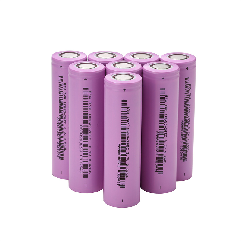
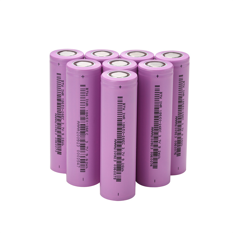
The 18650 is a cylindrical rechargeable battery format whose name is derived from its approximate dimensions: 18mm in diameter and 65mm in length. Actual maximum dimensions can vary slightly by model and manufacturer.
Cylindrical lithium-ion batteries are widely used in power tools and garden tools because their metal casing provides mechanical strength and their standardized form supports high-volume automated production. Samsung SDI identifies power tools and garden tools as established applications for cylindrical battery formats, while current high-power commercial cells continue to use the 18650 format.
A typical power-tool-grade 18650 cell may have:
A nominal voltage of approximately 3.6V or 3.7V
A charging voltage of up to approximately 4.2V, depending on chemistry
Capacity commonly selected to balance runtime and current output
A cylindrical steel casing
Flat-top terminals for welded battery pack assembly
High continuous and pulse discharge capability
Low internal resistance
Controlled temperature rise under load
Specifications vary significantly between models. Battery pack designers must always use the official cell datasheet rather than applying generic 18650 parameters.
Power tools place very different demands on batteries compared with consumer electronics. A drill may require a large current surge when starting, while a grinder or circular saw may operate under sustained high load. The battery must provide this power without excessive voltage drop or overheating.
A suitable high-drain 18650 cell can provide substantial current from a relatively small package. For example, one current commercial power cell lists a typical capacity of 2.8Ah and a discharge-current specification of 35A, demonstrating how power-oriented cells prioritize current capability alongside usable capacity.
The exact permissible current still depends on temperature, cooling conditions, cut-off voltage, pack construction and the manufacturer’s test conditions.
The 18650 format benefits from established production, testing and PACK assembly processes. Battery manufacturers can use automated equipment for:
Cell sorting
Insulation-ring installation
Cell-holder assembly
Resistance welding
Nickel-strip or busbar connection
Voltage measurement
BMS installation
Battery pack testing
This manufacturing maturity can help power tool brands control production efficiency and scale output.
Individual 18650 cells can be connected in series to increase voltage and in parallel to increase capacity and available current.
This allows manufacturers to develop battery platforms for different tool categories while continuing to use the same basic cell format.
The steel cylindrical shell offers resistance to vibration and mechanical stress. This is valuable for power tools used on construction sites, in workshops and in outdoor environments.
The completed pack must still include proper cell holders, shock protection, insulation and enclosure design.
A manufacturer can use 18650 cells to create a family of interchangeable battery packs with different capacities. For example, the same tool platform may offer compact packs for lighter work and larger packs for longer runtime.
One of the most common mistakes in power tool battery development is choosing the cell with the highest advertised capacity.
High capacity does not necessarily mean high power.
Energy-oriented cells are designed primarily to maximize runtime. They may be suitable for:
LED lighting
Portable electronics
Low-current backup devices
Energy-oriented battery packs
Equipment with a steady, moderate load
These cells may experience excessive voltage sag or heating when used in demanding power tools.
Power-oriented cells are developed to deliver higher continuous and pulse current. They are more suitable for:
Cordless drills
Impact wrenches
Rotary hammers
Angle grinders
Circular saws
Reciprocating saws
Lawn equipment
High-powered vacuum cleaners
A power-oriented cell may have a lower nominal capacity than an energy cell, but it can deliver greater usable power under load.
The correct cell should satisfy both the required runtime and the maximum load current.
Important selection parameters include:
| Parameter | Why It Matters |
|---|---|
| Nominal capacity | Influences theoretical runtime |
| Continuous discharge current | Determines sustained load capability |
| Pulse current | Affects starting and short-duration peak loads |
| Internal resistance | Influences voltage sag and heat generation |
| Discharge curve | Shows usable voltage under different loads |
| Cell temperature | Influences safety, performance and service life |
| Cycle life | Affects replacement frequency |
| Cell weight | Influences tool ergonomics |
| Charge rate | Influences charging time |
| Cut-off voltage | Must match the BMS and tool controller |
The first step is to identify the maximum electrical power required by the tool.
A simplified current estimate can be made by dividing tool power by battery voltage. However, real battery pack design must also account for motor efficiency, controller losses, voltage drop, startup current and transient overloads.
For example, a tool requiring 600W from an 18V-class battery may draw more than 33A at the battery pack level during operation. The current can rise further under startup, stall or heavy cutting conditions.
In a 5S2P battery pack, the load is divided between two parallel cell groups. Each parallel path would therefore need to support approximately half the pack current, assuming good cell and connection consistency.
Designers should reserve an appropriate current margin rather than operating every cell continuously at its absolute limit.
A lithium-ion battery pack’s advertised voltage often differs from its nominal and fully charged voltage.
The following examples assume cells with a nominal voltage around 3.6V and a maximum charge voltage around 4.2V. Exact values must be confirmed from the selected cell datasheet.
| Configuration | Nominal Pack Voltage | Approximate Fully Charged Voltage | Typical Positioning |
|---|---|---|---|
| 3S | 10.8V | 12.6V | Compact drills and light-duty tools |
| 4S | 14.4V | 16.8V | Medium-duty portable tools |
| 5S | 18V | 21V | Common cordless power tool platform |
| 6S | 21.6V | 25.2V | Higher-voltage tool systems |
| 10S | 36V | 42V | Lawn tools and heavy-duty equipment |
| 15S | 54V | 63V | High-power saws and outdoor equipment |
Marketing labels such as 12V, 20V Max, 40V Max or 60V Max may refer to different voltage conventions. Battery and tool manufacturers should clearly distinguish nominal voltage from maximum charged voltage.
Connecting cells in series increases battery pack voltage.
For example:
5 cells in series create an approximately 18V nominal pack
10 cells in series create an approximately 36V nominal pack
The capacity in ampere-hours remains equal to the capacity of one series group.
Connecting cells in parallel increases capacity and current capability.
For example, a 5S2P battery pack contains ten cells:
Five series groups establish the voltage
Two cells in each parallel group increase capacity
Current is shared between the parallel cells
A 5S3P pack contains fifteen cells and may offer longer runtime and lower current stress per cell, but it also increases pack size, weight and cost.
| Pack Configuration | Total Cells | Main Advantage | Possible Application |
|---|---|---|---|
| 3S1P | 3 | Compact and lightweight | Screwdrivers and small drills |
| 3S2P | 6 | Higher runtime | Compact professional tools |
| 5S1P | 5 | Lightweight 18V-class pack | Drills and impact drivers |
| 5S2P | 10 | Balanced runtime and power | Saws, grinders and drills |
| 5S3P | 15 | Longer runtime and lower cell load | Professional heavy-use tools |
| 10S2P | 20 | Higher-voltage output | Garden and high-power equipment |
The best configuration depends on motor power, required runtime, tool dimensions and acceptable pack weight.
Internal resistance is one of the most important parameters for power tool cells.
When a battery supplies high current, part of the voltage is lost inside the cell. This is commonly observed as voltage sag. Higher internal resistance generally leads to:
Greater voltage drop
Lower available motor power
Higher heat generation
Earlier BMS cut-off
Reduced usable battery capacity
Faster cell aging under heavy load
Two cells may have the same nominal capacity but perform very differently in an angle grinder or circular saw because of differences in internal resistance and discharge behavior.
Battery pack manufacturers should evaluate internal resistance at the cell level and after pack assembly.
Heat is produced by the cells, busbars, welded joints, MOSFETs and other electrical components. Poor thermal design can cause uneven aging or trigger protection during high-load operation.
Common heat sources include:
High cell current
Cell internal resistance
Undersized nickel strips or busbars
Poor weld quality
Loose terminal connections
High-resistance connectors
BMS MOSFET losses
Restricted airflow
Charging immediately after heavy use
A power tool battery pack may use:
Air channels between cells
Temperature-resistant cell holders
Thermally conductive materials
Temperature sensors near likely hot spots
Low-resistance busbars
Ventilation openings
Charger-controlled cooling
Software-based current reduction
Charging delays after high-temperature operation
Cooling only the outer cells is not sufficient if cells in the center of the pack reach a much higher temperature.
The BMS is essential for monitoring and protecting a lithium-ion power tool battery pack.
Core functions should include:
Cell overvoltage protection
Cell undervoltage protection
Charge overcurrent protection
Discharge overcurrent protection
Short-circuit protection
High-temperature protection
Low-temperature charging protection
Cell balancing
Pack-current monitoring
State-of-charge estimation
Communication with the tool or charger
The BMS must be matched to the actual motor and battery system. A protection board designed for low-current electronics is not suitable for a high-power drill or saw.
Power tools can produce short current peaks during:
Motor startup
Sudden acceleration
Blade engagement
Drilling into dense materials
Temporary overload
Motor stall
If the BMS threshold is too low, the tool may shut down during normal use. If the threshold is too high, the cells and electrical connections may be insufficiently protected.
The BMS should distinguish between an acceptable short-duration current peak and a dangerous sustained overload.
Battery packs are limited by their weakest cells.
Differences in capacity, voltage, internal resistance and self-discharge can cause one group to reach its voltage limit before the others. This reduces usable pack capacity and may lead to premature BMS protection.
Cells should be matched according to:
Production batch
Open-circuit voltage
Measured capacity
Internal resistance
Self-discharge
Discharge curve
Manufacturing date
Temperature behavior
Cell mixing should be avoided. Different models, capacities, brands, production batches or usage histories should not be combined within the same power tool battery pack.
Most industrial 18650 battery packs use welded connections rather than soldering directly to the cells.
Direct soldering can expose cells to excessive localized heat and may damage seals or internal structures.
Manufacturers should evaluate:
Nickel-strip thickness
Busbar material
Current-carrying capacity
Welding energy
Number and position of weld points
Contact resistance
Insulation around the positive terminal
Pack vibration
Corrosion resistance
Mechanical strain on welds
A battery cell with strong discharge capability cannot deliver its full performance if the connections create excessive resistance.
Every pilot pack should undergo temperature-rise testing at maximum continuous and peak load.
The charger must match the cell chemistry, series configuration and charging-current limit.
A typical lithium-ion charging process uses controlled current followed by controlled voltage, but charging parameters must follow the selected cell manufacturer’s specifications.
The charger should monitor:
Pack voltage
Charging current
Cell temperature
Connection status
Battery identification
Communication signals
Charging time
Abnormal voltage behavior
Charging a hot battery immediately after intensive tool use can accelerate degradation. Some battery systems delay or reduce charging until the cell temperature returns to an acceptable range.
Samsung SDI warns that lithium-ion cells contain high energy and can cause injury or property damage when abused or improperly handled, reinforcing the need to follow model-specific charging, usage and handling guidance.
Battery safety cannot be evaluated only at the individual cell level. The completed pack, charger and tool must function as a coordinated system.
Relevant evaluation may include:
External short-circuit testing
Overcharge testing
Forced discharge testing
Drop testing
Vibration testing
Mechanical shock testing
Thermal testing
Abnormal charging
Motor-stall testing
Charger fault testing
Enclosure impact testing
Terminal-strength testing
IEC 62133-2 covers safety requirements and tests for portable sealed secondary lithium cells and batteries under intended use and reasonably foreseeable misuse. UL Solutions also provides dedicated testing and certification services for batteries and packs used in power tools and lawn-and-garden machinery.
Requirements vary by market and product. Manufacturers should confirm the applicable standards with a qualified testing organization before finalizing the battery design.
Power tool batteries containing lithium-ion cells are regulated during transportation.
Before commercial shipment, manufacturers may need:
UN38.3 test documentation
Cell and pack specifications
Safety data sheets
Watt-hour ratings
Short-circuit-resistant packaging
Terminal protection
Appropriate labels and marks
Compliant air, sea or road transport packaging
A cell-level UN38.3 report does not automatically eliminate pack-level responsibilities. The final battery configuration, packaging method and transport route must be evaluated.
Drills require repeated acceleration and moderate-to-high torque. Cell selection should balance power, runtime and pack weight.
These tools generate frequent current pulses. Low internal resistance and strong pulse-current performance are particularly important.
Grinders can draw sustained high current. Continuous discharge capability and thermal management are often more important than maximum nominal capacity.
Saws experience high startup current and changing mechanical loads. Voltage stability under load directly affects cutting performance.
Rotary hammers require high power and may operate continuously on construction sites. Strong connections, vibration resistance and thermal protection are essential.
Blowers, trimmers and lawn equipment may use higher-voltage battery platforms. Environmental sealing, temperature adaptability and longer runtime become important selection factors.
The 21700 format is increasingly used in high-power battery systems, but 18650 cells continue to offer practical advantages.
| Comparison Factor | 18650 Cells | 21700 Cells |
|---|---|---|
| Approximate size | 18 × 65mm format | 21 × 70mm format |
| Pack design | Compact and mature | Fewer cells may be needed |
| Production equipment | Widely available | May require different tooling |
| Cell weight | Lower per cell | Higher per cell |
| Thermal surface distribution | More individual cells | Larger energy per cell |
| Existing tool platforms | Strong compatibility | Often used for new platforms |
| Supply options | Broad mature selection | Growing high-power selection |
The correct choice depends on whether the manufacturer is upgrading an existing 18650 platform or developing a completely new battery system.
Power tool manufacturers should evaluate more than cell price.
Important supplier criteria include:
Complete model datasheets
Defined continuous and pulse-current limits
Discharge curves at multiple currents
Temperature-rise data
Cycle-life conditions
Charging specifications
Application engineering support
Capacity tolerances
Internal-resistance tolerances
Voltage consistency
Batch traceability
Self-discharge inspection
Production-date control
Applicable certification information
UN38.3 test documents
Safety data sheets
Quality inspection reports
Transport documentation
Stable production capacity
Consistent long-term model availability
Sample support
Pilot-order capability
Mass-production lead time
Export packaging experience
A qualified supplier may support:
Cell model selection
Series-parallel configuration
Cell sorting standards
Battery module design
BMS matching
Busbar recommendations
Thermal management
Custom battery packs
OEM or ODM production
To receive an accurate cell recommendation, buyers should provide:
Tool type
Motor-rated power
Operating voltage
Maximum continuous current
Peak or stall current
Expected runtime
Battery pack dimensions
Target pack weight
Series-parallel configuration
Charging time
Operating temperature
Expected cycle life
Annual purchase volume
Required certifications
Destination market
Providing only the required capacity is not sufficient for selecting a safe and effective power-tool-grade cell.
A 3500mAh energy cell may perform worse in a grinder than a lower-capacity high-power cell.
The tool may lose torque or trigger undervoltage protection even when the battery still contains energy.
A low-current BMS can shut down under normal startup or stall conditions.
Undersized conductors create heat and reduce delivered power.
Combining different models or batches increases imbalance risk.
One sensor placed far from the hottest cell may not provide effective protection.
Cell specifications alone cannot predict performance inside the final enclosure.
No. Power tools require high-drain cells capable of delivering substantial continuous and pulse current. Energy-oriented cells intended for laptops or low-current devices may overheat or experience excessive voltage sag.
There is no single best capacity. The cell must provide sufficient current while meeting runtime, size, weight and cycle-life requirements. Power capability should be evaluated before selecting the highest available capacity.
An 18V nominal lithium-ion power tool pack commonly uses five series-connected cell groups. A 5S1P pack contains five cells, while a 5S2P pack contains ten cells.
Five lithium-ion cell groups provide approximately 18V nominal voltage and approximately 21V when fully charged, depending on the selected cells. Some brands market the platform by nominal voltage, while others use a rounded maximum voltage.
This is not recommended unless the exact cell specifications are verified for the tool’s current demand. Many laptop cells are optimized for energy capacity rather than high-power discharge.
Commercial power tool packs usually use unprotected industrial cells managed by a pack-level BMS. Individual protected cells may have different dimensions and current limits and are generally not intended for welded multi-cell tool packs.
Common causes include excessive current, high internal resistance, poor cell consistency, undersized busbars, defective welds, insufficient airflow, BMS losses and charging while the pack is still hot.
No. Cells in the same pack should use the same model, production batch and matched electrical characteristics.
Manufacturers should test capacity, current capability, voltage sag, temperature rise, BMS protection, charger compatibility, vibration resistance, drop performance, motor stall and complete tool operation.
Power tools using 18650 cells can achieve compact size, strong power output and flexible battery pack design, but reliable performance depends on selecting the correct high-drain cell and integrating it into a properly engineered system.
Battery manufacturers should evaluate continuous current, pulse current, internal resistance, voltage sag, temperature rise, cell consistency and cycle life alongside nominal capacity. The BMS, busbars, welding process, charger and thermal structure must then be matched to the actual operating profile of the tool.
For a new cordless drill, saw, grinder, impact wrench or garden tool project, provide the tool voltage, motor power, peak current, required runtime, pack dimensions and estimated purchase quantity. A suitable 18650 cell and battery pack configuration can then be evaluated for sample testing and mass-production integration.